Viewer3d - Colour mapping
Each channel of an RGB or RGB16 image is processed individually and mapped to the range [0..255]. These channels are then combined to a resulting RGB value. Individual channels can be selected from the menu Mapping.
Voxel values of greyscale images of all types are first mapped to a value from the range [0..255], which defines an index to a colour pallete. This allows displaying of greyscale images in colours. The possibilities are:
- Gray - no pallete is used. Only grey values are shown
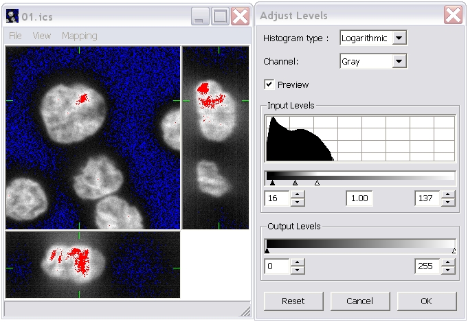
- Saturation - voxels mapped to 0 are shown in blue colour, voxels mapped to 255 are shown in red colour, and all other values are shown in grey. This enables visualization of under- and over-exposed values. For example this choice together with Percentil stretch shows 5% of the lowest values in blue and 5% of the greatest values in red.
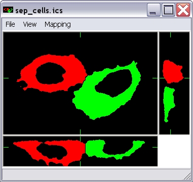
- Labels - a distinct colour is assigned to each value. It is suitable for displaying of indexed (labelled) images after segmentation.
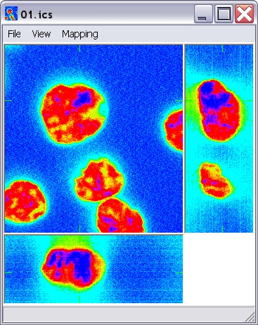
- Periodic - a pallete with gradual colour and the same colour for 0 and 255. This mode is, for example, good for the visualization of orientations or intensity levels in images.
- Pallete - a user defined pallete can be read from a file.